Well Flow Loop
Contact us

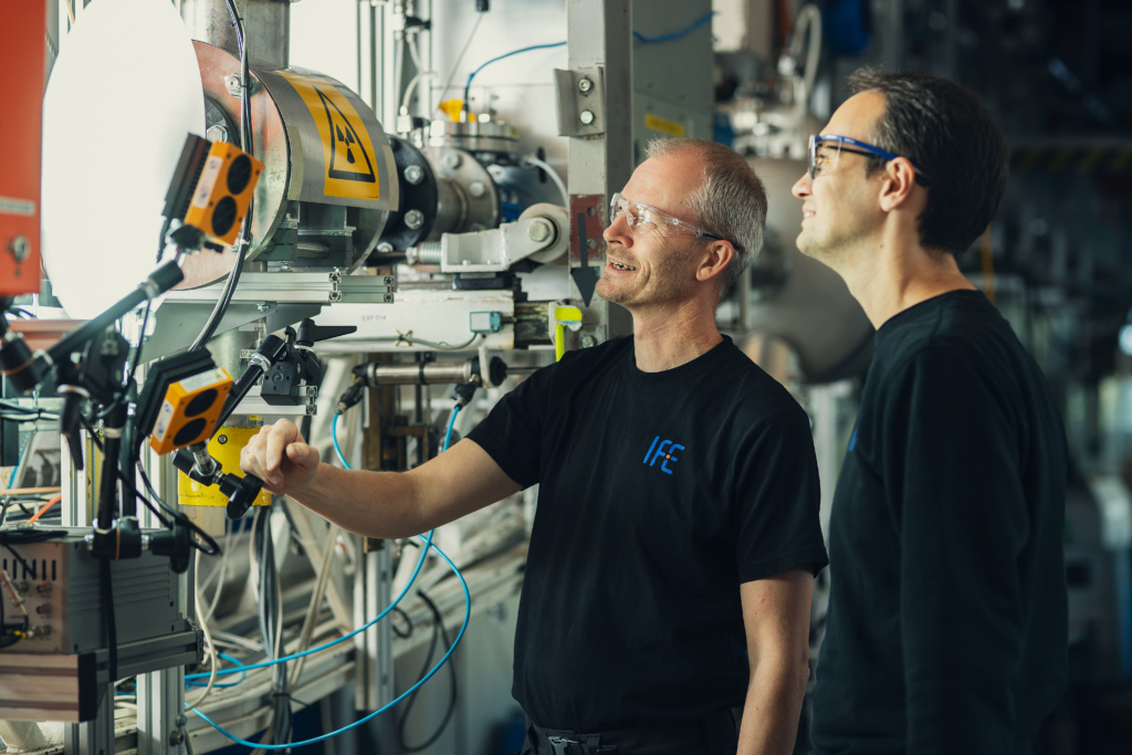
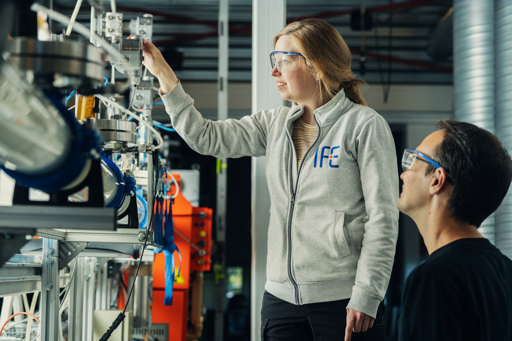
The Well Flow Loop is part of the Norwegian Infrastructure for Multiphase Flows, providing advanced experimental capabilities for multiphase flow research. Combining flexible operating conditions with state-of-the-art measurement technologies, the facility enables detailed investigation of flow phenomena relevant to energy, process, and subsea applications.
Description
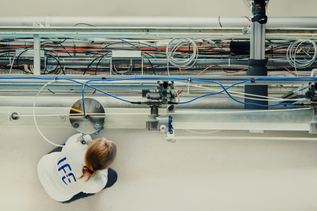
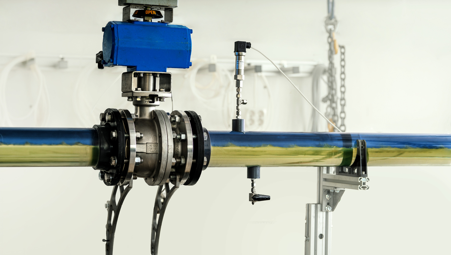
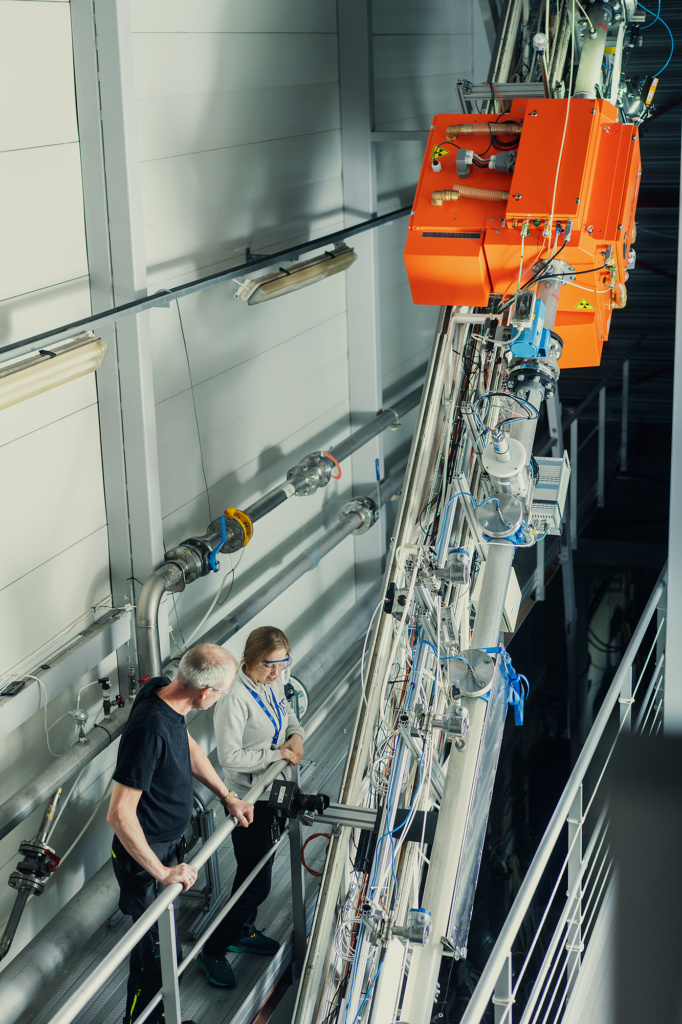
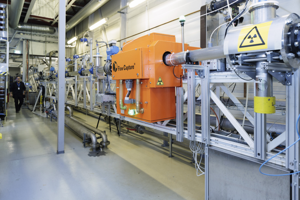
The loop is designed for multiphase flow research in pipes with inclinations ranging from horizontal to vertical, supporting both upward and downward flow configurations. The facility comprises of a transparent test section, a return section, a gas–liquid separator, an oil–water separator, pumps, and compressors.
The loop supports three-phase flow experiments involving oil, water, and gas. Experimental campaigns may also include solid particles, crude oil, and emulsions. Facility operation and process control are managed through a fully integrated computer system, which also provides automated data acquisition.
The loop was inaugurated in June 1994 and has undergone continuous development and upgrades since commissioning. The facility has contributed to the development and validation of OLGA, a key simulator tool used for flow assurance and multiphase transport that enabled subsea oil production.
The facility is currently being upgraded to reduce environmental impact through replacement of its model gas, sulphur hexafluoride SF₆, with krypton as the gas phase. Krypton is an inert gas with negligible climate impact. As part of this upgrade, the operating pressure range will be increased from 10 bara to 16 bara, enabling a gas density of approximately 55 kg/m³, representative of natural gas at production pressure.
Instrumentation
- Flow rate meters (ultrasonic, Coriolis, and electromagnetic)
- Density meters
- Pressure sensors
- Differential pressure transducers for pressure gradient measurements
- Broad-beam gamma densitometers for measurement of phase fractions (liquid/gas and oil/water/gas)
- X-ray CT systems for measurement of holdup, fluid distribution, and interface structures
- High-speed video cameras for flow visualization
- Laser Doppler anemometer for velocity measurements
- Iso-kinetic probes for droplet fraction measurements
Technical Specifications
- Loop material: AISI 316
- Fluids: Water, oil, and gas
- Operational pressure: Maximum 16 bara
- Test section dimensions: ID 100 mm, length 45 m @ ±2°, 25 m @ ±5°, 15 m @ ±90°
- Test section material: Transparent PVC and glass sections
- Variable inclination: −90° to +90° (fully horizontal to fully vertical: upwards and downwards)
- Gas phase: Krypton
- Superficial gas velocity range: 0.5–14 m/s
- Superficial oil velocity range: 0–2 m/s
- Superficial water velocity range: 0–2 m/s